Trolling Motor Plug Wiring Diagram
Rj11 Socket Wiring Diagram Australia, How to punch down an RJ11 Telephone Jack, 6.36 MB, 04:38, 387,634, CableSupply.com, 2009-08-05T00:16:07.000000Z, 19, Rj11 Socket Wiring Diagram Australia | Computacion, Redes de computadoras, Computadoras, www.pinterest.com.mx, 728 x 783, jpeg, rj11 wiring rj45 diagram cable ethernet usb jack pinout adapter cat5 female male convert using rs485 cat wires code socket, 20, rj11-socket-wiring-diagram-australia, Anime Arts
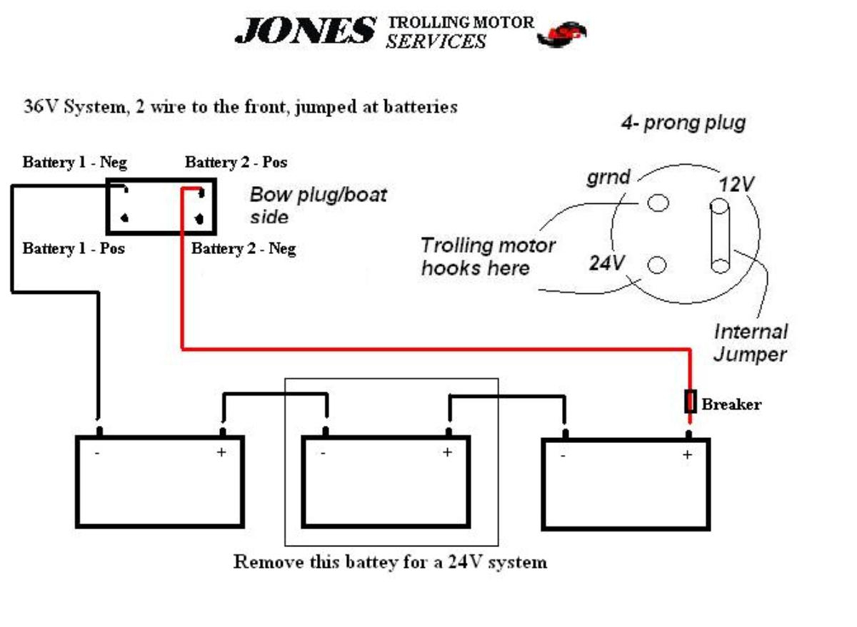
4 prong trolling motor plug wiring diagram source: Have the right tools handy just like any other diy job, you want to ensure you have the right tools to do the job. Make sure that the trolling motor is disconnected. Wire in series only as directed in wiring diagram, to provide 48 volts.
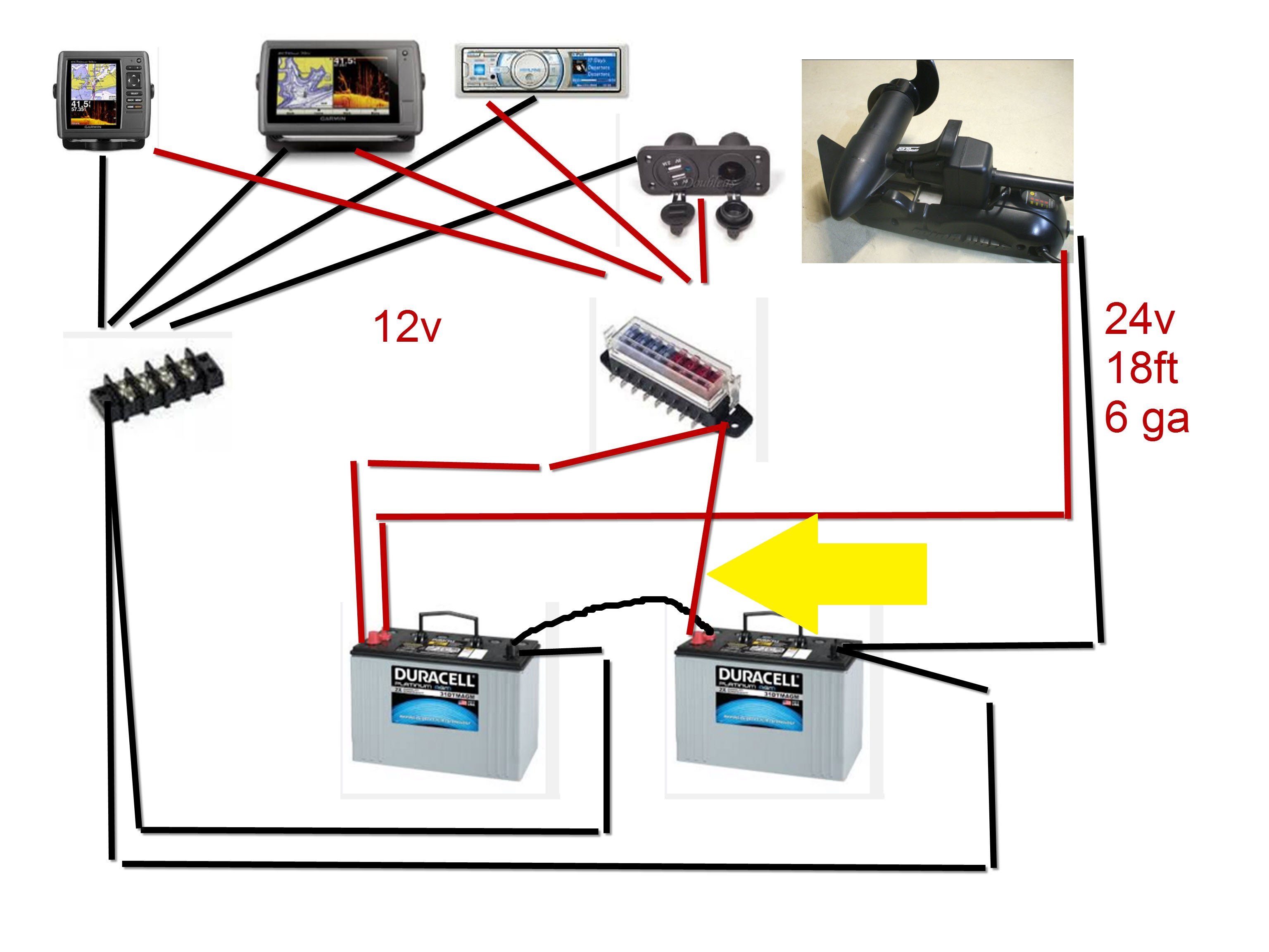
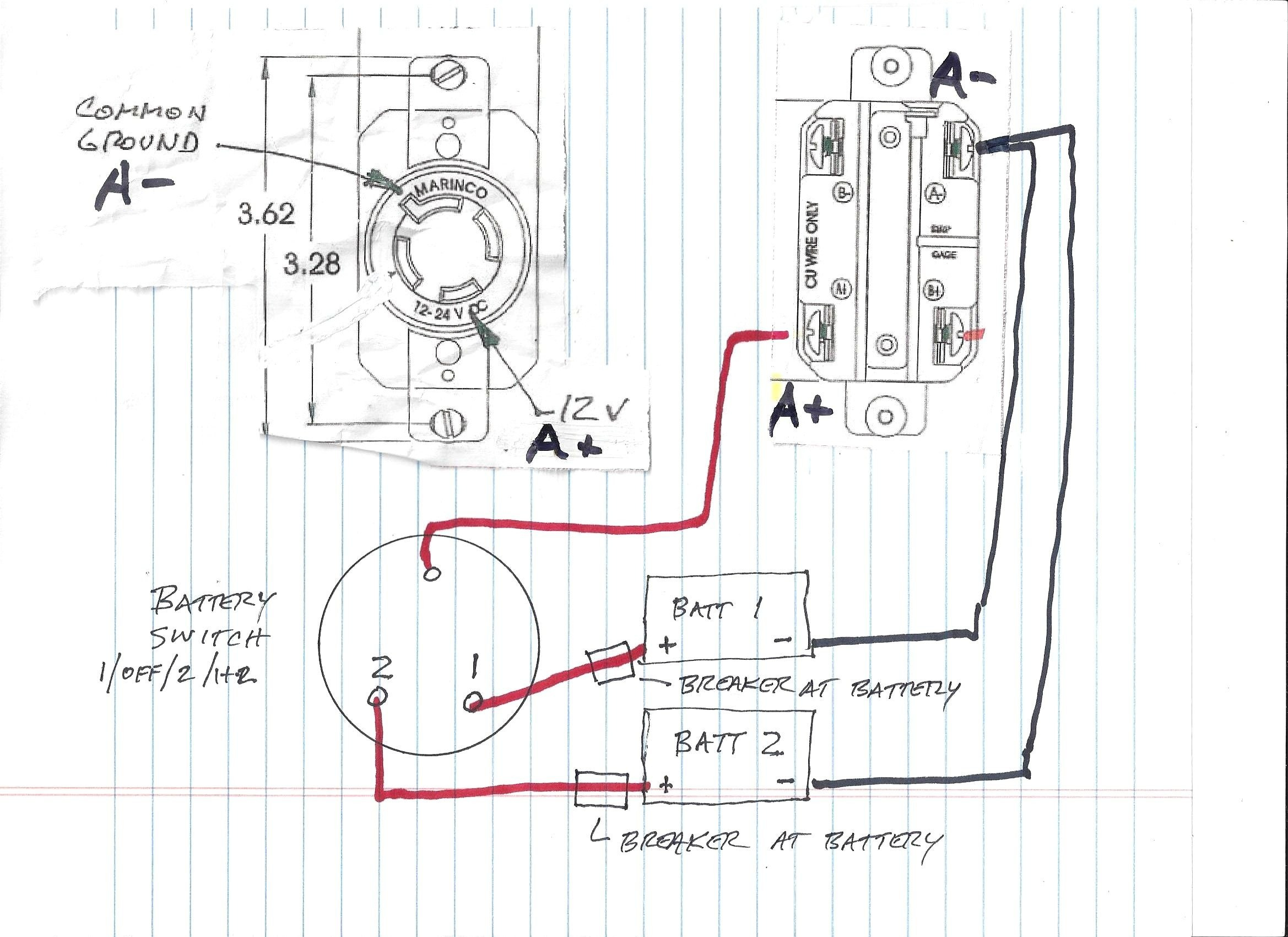
12/24 volt switch trolling motor wiring diagram the purpose of the 12/24 switch is to put the batteries in parallel so they can be charged by a single charger. If you have a multiple bank charger, it is not needed. Connect the negative terminal of battery #1 to negative on the trolling motor. 3 wire trolling motor wiring diagram. To properly read a electrical wiring diagram, one offers to learn how the particular components in the system operate. For instance , if a module is usually powered up and it sends out a new signal of half the voltage and the technician will not know. 3 prong marinco plug wiring diagram, along with 3 prong marinco plug wiring diagram also 24 volt wiring diagram for trolling motor as well as motorguide trolling motor schematics furthermore 24v trolling motor wiring diagram in addition wiring diagram 50 plug together with in addition l14 30 wiring diagram together with 50 twist lock plug wiring diagram as well as. Connect the trolling motors positive (+) power cable to the terminal marked "aux" on the circuit (see diagrams below for 12, 24 and 36v use. ) have the series link made at the trolling motor plug or plug receptacle. Attwood marine offers a broad range of boating and marine accessories.
Marinco 3 Prong Trolling Motor Plug Wiring Diagram
4 Prong Trolling Motor Plug Wiring Diagram – Collection | Wiring Collection

4 Wire 24V System - 4 Prong Trolling Motor Plug Wiring Diagram - Wiring Diagram

Trolling Motor Plug Mkr-18 Wiring Diagram
Minn Kota Trolling Motor Plug And Receptacle Wiring Diagram | Wiring Diagram

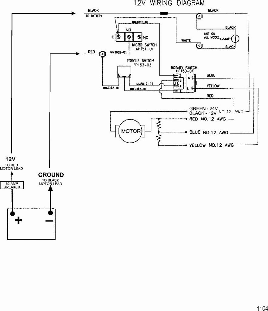
Motorguide 12 24 Volt Trolling Motor Wiring Diagram

Marinco 3 Prong Trolling Motor Plug Wiring Diagram

4 Wire 24V System - 4 Prong Trolling Motor Plug Wiring Diagram - Cadician's Blog

4 Prong Trolling Motor Plug Wiring Diagram - Diagram For You
30 How To Wire A 24 Volt Trolling Motor Diagram - Wire Diagram Source Information

